
Videos
In the circuit of Fig. 9.47, find io when:
- (a) ω = 1 rad/s
- (b) ω = 5 rad/s
- (c) ω = 10 rad/s
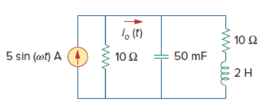
Figure 9.47
(a)
Find the value of the current
Answer to Problem 40P
The value of the current
Explanation of Solution
Given data:
Refer to Figure 9.47 in the textbook.
The value of the angular frequency
Formula used:
Write the expression to calculate the impedance of the passive elements resistor, inductor and capacitor.
Here,
Calculation:
The given circuit is redrawn as Figure 1.
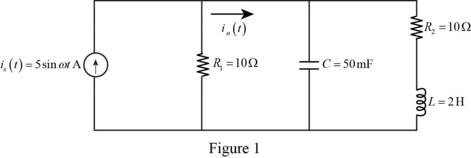
Refer to Figure 1, the current equation is,
Convert the given current into phasor form.
Substitute
Substitute
Substitute
Substitute
The Figure 1 is redrawn as impedance circuit in the following Figure 2.
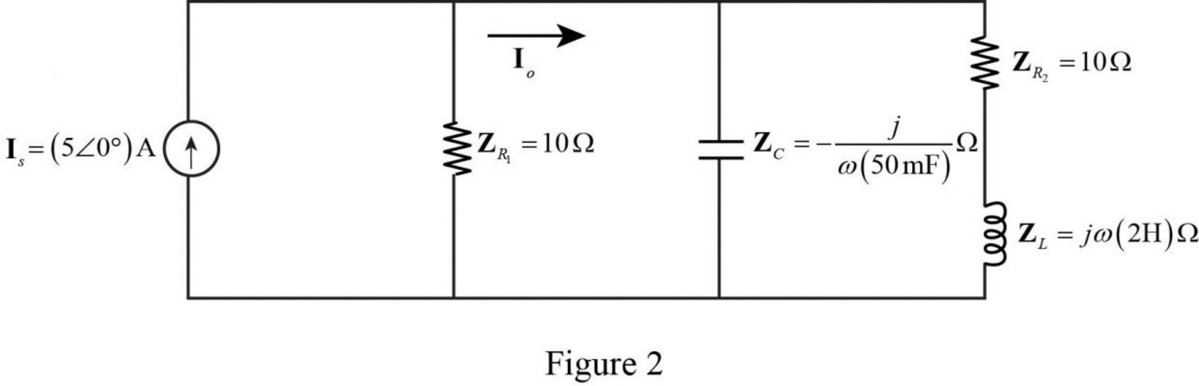
Write the expression to obtain the source transformation from current to voltage.
Substitute
Based upon the source transformation, the Figure 2 is reduced as the following Figure3.
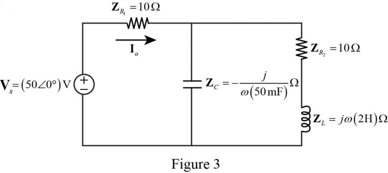
Refer to Figure 3, the series connected impedances
Therefore, the total equivalent impedance is calculated as follows.
Substitute
Substitute
Substitute
The reduced circuit of Figure 3 is drawn as Figure 4.
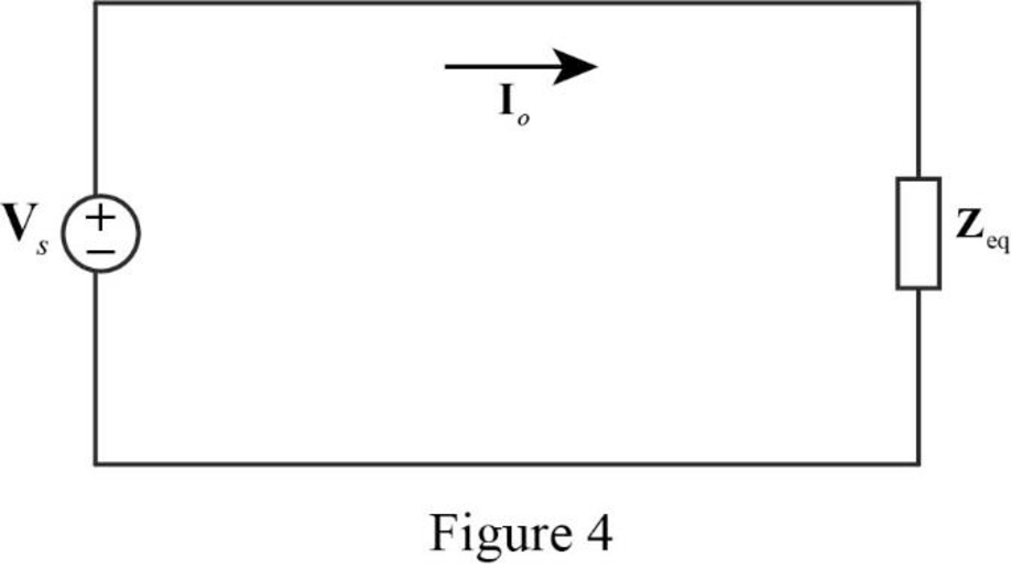
Refer to Figure 4, the current
Substitute
Convert the above equation from phasor form to time domain form.
Substitute
Conclusion:
Thus, the value of the current
(b)
Find the value of the current
Answer to Problem 40P
The value of the current
Explanation of Solution
Given data:
The value of the angular frequency
Calculation:
Substitute
Substitute
Substitute
Refer to Figure 4, the current
Substitute
Convert the above equation from phasor form to time domain form.
Substitute
Conclusion:
Thus, the value of the current
(c)
Find the value of the current
Answer to Problem 40P
The value of the current
Explanation of Solution
Given data:
The value of the angular frequency
Calculation:
Substitute
Substitute
Substitute
Refer to Figure 4, the current
Substitute
Convert the above equation from phasor form to time domain form.
Substitute
Conclusion:
Thus, the value of the current
Want to see more full solutions like this?
Chapter 9 Solutions
Fundamentals of Electric Circuits


- A series circuit contains a 20-Ω resistor and a capacitor with a capacitance of 110.5 µF. If the circuit has a frequency of 60 Hz, what is the total impedance of the circuit?arrow_forwardRLC Network Question If the voltage source is sinusoidal, then the input voltage (r.m.s.) is: -14V->> > HH -m C ←8V→>> ww R Larrow_forward9:06 4 * A • O N ll 74% * Required Answer all questions Find output response y(t) for the frequency response H(w)=1/(2+jw) and the input signal x(t)=0(-2t) * Non of all the above Option (3) option (2) 1 e-"u(t) 2 Option 3 1 e"u(t) IIarrow_forward
- Q2) Which of the following series is converge or diverge n=1 n 27arrow_forwardAn RLC circuit has Z = 6 + j8 ohms. Its susceptance is ____Siemens. choices: 0.08, 0.06, -0.08, 0.1arrow_forwardThe equivalent capacitance at terminals a-b in the circuit given is 85 F, then the value of C is 14 F C 80 F bo 18.08 mF 4.92 F 4.92 mF O 6.2 Farrow_forward
- 12- Self commutated circuit drawn 200A maximum from 200 V source voltage. Find the value of the inductance if the ringing frequency is 2000 rad/s * L=1mH L=0.5 mH L=24 mHarrow_forwardd) T/ 30 sec 10. For an energy signal a) E-0 b) P= ∞ c) E= 0 d) P-0 11 Te the cional x(n)=1/n + 4) De We Start TOSHIBAarrow_forwarduo 7:59 A docs.google.com * ll. Classroom > naturel frequency. C(t) = 6. 66e¬10t – 6, 66 e-4 1 Add file Q2) for block diagram below find G1 G2 G3 H 1 Add file Q3) find CSS and draw the signal of response for block diagram below if the input was 5 ramp الرقم السادس S (S+15) R- 2 1 Add file Submitarrow_forward
- Draw a PLA circuit to impliment the functions F, = AB+ AC+ĀBC and F = (AC + AB + BC)arrow_forwardDetermine if each statement is True or False; if false, please explain whya) A forced oscillator is when a system is being yelled at to perform a specific motion.b) Impedance is a measure of the total resistance a RLC series circuit has towards current.c) The phase angle tells us how “out-of-phase” the charge on the capacitor iswith the driving voltage.arrow_forwardIn a series RLC circuit, the larger reactance determines the net reactance of the circuit. Select one: O True Falsearrow_forward
 Introductory Circuit Analysis (13th Edition)Electrical EngineeringISBN:9780133923605Author:Robert L. BoylestadPublisher:PEARSON
 Delmar's Standard Textbook Of ElectricityElectrical EngineeringISBN:9781337900348Author:Stephen L. HermanPublisher:Cengage Learning
 Programmable Logic ControllersElectrical EngineeringISBN:9780073373843Author:Frank D. PetruzellaPublisher:McGraw-Hill Education
 Fundamentals of Electric CircuitsElectrical EngineeringISBN:9780078028229Author:Charles K Alexander, Matthew SadikuPublisher:McGraw-Hill Education
 Electric Circuits. (11th Edition)Electrical EngineeringISBN:9780134746968Author:James W. Nilsson, Susan RiedelPublisher:PEARSON
 Engineering ElectromagneticsElectrical EngineeringISBN:9780078028151Author:Hayt, William H. (william Hart), Jr, BUCK, John A.Publisher:Mcgraw-hill Education,